Page 1 2
Go  | New  | Find  | Notify  | Tools  | Reply  |  |
| Member |
I think wiring the AC that way would be a mistake, regardless of which polarity you wire the AC, there's a switch configuration where a not-running motor has hot AC going to it. I think the BEST way to do it would be to use two DPST relays, one for each motor, with each relay switching both AC hot and neutral. That way if a motor is off it is completely isolated from the AC circuit. Stuff like this is sometimes wired the same way but with only SPST relays on the AC hot wires. The problem with this is that if you get the AC polarity screwed up, the motors can be "hot" but turned off. You'd do the ON-OFF switching in the footswitch. The 9V supply goes to the ON-OFF footswitch. The output of the ON-OFF footswitch goes to the ON-ON high/low footswitch, the two outputs of which go to the TRS jack. | |||
|
| Member |
 | |||
|
| Member |
Also, I would make sure to use an electrically isolated jack on the Leslie cabinet and not connect the DC ground/TRS sleeve to any part of the AC circuit or any neutral or ground in the cabinet. | |||
|
W07VH5 |
I see what you mean. I'll redraw it. I'll have to specify non-latching relays in this case. Much simpler and safer, thank you. | |||
|
| Member |
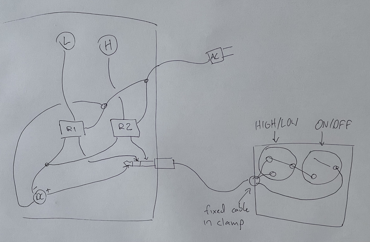
Also, if you don't want to rely on pedalboard power, you could set it up the way a traditional footswitch works. You'd put a DC power supply in the Leslie cab to match the operating voltage of your relays (now it doesn't have to be 9V because you aren't working off a pedalboard power supply), and run the DC+ voltage on the third conductor instead of ground. You'd want to use a fixed cable on the footswitch side (using a plug on that end risks shorting the power supply, which wouldn't hurt you but could kill the power supply) and you'd want to put the DC+ voltage on the tip of the TRS jack in the Leslie cab (so that you wouldn't short it when plugging the footswitch in). Here's a quick sketch, all the AC "wires" are actually both hot and neutral, I just left them a single line to make the drawing simpler. In a lot of ways, I think this is actually the best solution, although it's marginally more complicated and marginally more expensive.  If you want LED indicators on the footswitch, you either need a ground (so use a TRRS four-conductor cable and add a ground wire back in) or you need to be very careful about power supply and relay voltages, relay current demands, LED forward voltage and current limits, and wire the LEDs inline in the circuit (which is probably too fussy to be worth it - I'd just go TRRS four-conductor). I am happy to draw out a proper circuit diagram for either scenario and talk to you about component selection if you want (if you get relay boards, they're pretty plug-and-play, but LEDs generally require some care in selection and other components around them). | |||
|
W07VH5 |
I’ve been thinking about it and, since I need the 9vdc at the foot control for the indicator LEDs, I’m going to run the DC between the foot control and the cabinet. Seems much simpler. Now to find the correct relays. | |||
|
| Member |
If you use a TRRS jack and four-conductor cable, you can keep the power supply in the Leslie cab and use LED indicators in the footswitch with no special care in exactly the same way you would with the power supply connected to the footswitch. That has the advantage of keeping everything entirely self-contained so that you can use it off a pedalboard and without any additional power supply. | |||
|
| Powered by Social Strata | Page 1 2 |
| Please Wait. Your request is being processed... |
|
© SIGforum 2025